Site Development Plan with Topographic Contours and Utility Layout
Description
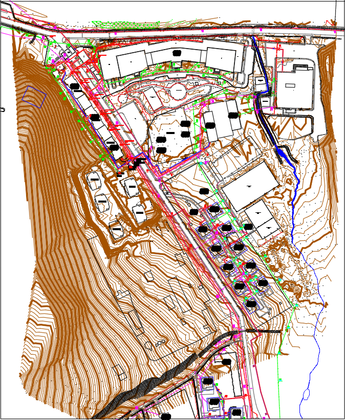
This detailed Site Development Plan DWG AutoCAD Topographic Layout presents a complete visualization of a sloped development site featuring clearly marked contour elevations ranging across the entire terrain. The drawing includes road alignments, approximately 6 to 8 meter-wide circulation paths, plot divisions, retaining zones, and structured building footprints arranged along the natural topography. Utility corridors, including drainage routes, service lines, landscape zones, and site circulation elements, are precisely layered, ensuring seamless coordination for architects, civil engineers, and urban planners. The map also highlights terrain gradients, cut and fill areas, and natural water flow paths, essential for site analysis and infrastructure planning.
This AutoCAD DWG delivers all major site planning components required for efficient project execution, including topographic curves, proposed construction footprints, vehicular access, and networked utility lines. The layout supports accurate quantity calculations, design validation, and engineering decision-making for land development projects. Ideal for architects, engineers, designers, BIM teams, and planning consultants, this file helps users optimize land use, evaluate terrain behavior, and design structurally sound developments.

Uploaded by:
Eiz
Luna